-
Disconnect Negative battery terminal.
-
Remove Battery cable positive terminal from Starter solenoid. At
the same time, remove second wire connected to positive terminal of solenoid.
Disconnect spade terminal from top of Starter solenoid.
-
Disconnect all plugs and terminals from Alternator.
-
Remove Alternator. Retain Alternator belt.
-
Remove lower alternator bracket from block by removing 2 bolts and 1
nut. Retain the nut and bolts
-
Detach fusible link assembly from electrical shelf.
-
Detach electrical shelf assembly from fenderwell by removing 4 bolts.
-
Unplug voltage regulator from wiring harness at provided connector.
Remove voltage regulator from electrical shelf assembly. Disconnect any
remaining connectors on the electrical shelf. Remove electrical shelf from car.
-
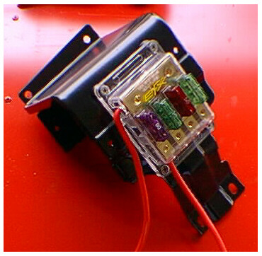 Install Fuse center onto electrical shelf
in the following manner. See picture for positioning information. Position solid bus
bar towards the top of the shelf, and the 4 separate bars towards the bottom. Note -
The bottom will have 4 Allen screws and 4 openings with 1 solid red wire attached.
The side of the fuse center that has the 2 red wires and the 80 amp fuse will go towards
the front of the car. Center the new Fuse center on side of electrical shelf
assembly where old fusible link assembly used to mount. Mark holes, and drill for
new screws. After drilling attach the fuse center to the electrical shelf by putting
the screws through the screw openings in the fuse center, then slide the rubber insulating
standoffs onto the screws. push screws through drilled holes and attach self locking
nuts to screws. Tighten nuts until a slight amount of compression is noted on the
rubber standoffs. Do not overtighten. Overtightening will cause the fuse
center to bow in the middle, and could cause premature failure. Install Fuse center onto electrical shelf
in the following manner. See picture for positioning information. Position solid bus
bar towards the top of the shelf, and the 4 separate bars towards the bottom. Note -
The bottom will have 4 Allen screws and 4 openings with 1 solid red wire attached.
The side of the fuse center that has the 2 red wires and the 80 amp fuse will go towards
the front of the car. Center the new Fuse center on side of electrical shelf
assembly where old fusible link assembly used to mount. Mark holes, and drill for
new screws. After drilling attach the fuse center to the electrical shelf by putting
the screws through the screw openings in the fuse center, then slide the rubber insulating
standoffs onto the screws. push screws through drilled holes and attach self locking
nuts to screws. Tighten nuts until a slight amount of compression is noted on the
rubber standoffs. Do not overtighten. Overtightening will cause the fuse
center to bow in the middle, and could cause premature failure.
-
Place electrical shelf assembly to the side. Remove old
electrical tape from wiring harness. Start at the firewall below the battery, and
continue until all wiring is exposed up to the alternator. It is not necessary to
continue past the alternator. Make sure that all tape is removed from wires leading
to fusible link assembly.
-
 See picture at right. Label only the
wires that are white with a red stripe. From the right fenderwell looking down,
label the wire at position 4 as number 4. Label the wire at position 3 as
number 3. Label the wire at position 2 as number 2. The thickest white wire
with a red stripe does not need to be labeled. Cut all white with red striped wires
1/2 inch below bottom of fusible link block. See picture at right. Label only the
wires that are white with a red stripe. From the right fenderwell looking down,
label the wire at position 4 as number 4. Label the wire at position 3 as
number 3. Label the wire at position 2 as number 2. The thickest white wire
with a red stripe does not need to be labeled. Cut all white with red striped wires
1/2 inch below bottom of fusible link block.
-
Separate the white wire that comes from Starter solenoid positive
terminal from the rest of the wiring harness. Separate white wires that come from
fusible link assembly from the rest of the harness. Remove old fusible link assembly
from car. Old parts will not be needed and may be discarded.
-
Locate white with red stripe wire that comes from the alternator.
Follow down the wire until it branches into 3 wires. Note that all 3 branches
are different sizes. The thickest wire goes to the old fusible link assembly and can
be ignored. The thinnest wire goes to the old voltage regulator, and can be ignored.
The medium sized wire goes all the way straight to the firewall, and eventually
connects to the fuse panel inside the car. Label this wire as Main, and cut it 1
inch from connection with alternator wire.
-
 Locate voltage regulator plug
near battery. Hold plug in the position shown. Locate wire that corresponds to
position 1. Label this wire as L. Cut wire 1 inch below plug. Locate
wire that corresponds to position 3. This wire should be yellow. Label this
wire N1. Cut wire 1 inch below plug. Cut remaining wires 1 inch below bottom
of plug. These wires will not be needed. Discard plug. Locate voltage regulator plug
near battery. Hold plug in the position shown. Locate wire that corresponds to
position 1. Label this wire as L. Cut wire 1 inch below plug. Locate
wire that corresponds to position 3. This wire should be yellow. Label this
wire N1. Cut wire 1 inch below plug. Cut remaining wires 1 inch below bottom
of plug. These wires will not be needed. Discard plug.
-
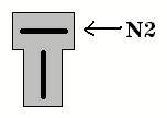 Locate the two wire "T" plug from alternator. Locate yellow wire at the
top of the "T". Label this wire as N2. Cut this wire 1 inch from
"T" plug. Discard "T" plug. Locate the two wire "T" plug from alternator. Locate yellow wire at the
top of the "T". Label this wire as N2. Cut this wire 1 inch from
"T" plug. Discard "T" plug.
-
Locate wires labeled 2, 3, and 4. These wires are white with a
red stripe. Strip insulation 3/8 inch from the end of the wire. Tin these
wires with solder.
TIP: Tinning involves heating the exposed wire and adding a small amount
of solder. Do not overheat wire. This will cause the insulation to melt.
Make sure soldering iron is hot, and flow solder onto the tip. Once the tip
has molten solder on it, touch the exposed wire with the molten solder and tip.
After a moment, the wire should be hot enough to add solder.
-
Install electrical shelf with new fuse center into car using 4 bolts.
Attach any auxiliary plugs that were removed during disassembly.
-
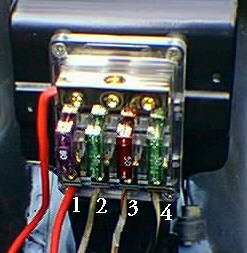 Route wires labeled 2, 3, and 4 to the bottom of the fuse center.
Insert wire labeled 2 into the position shown in the photograph. This is the first
empty wire terminal connection next to the solid red wire coming from the bottom.
Insert wire far enough that it will make solid contact with the Allen screw.
Tighten screw until wire is crushed and cannot be moved. Insert wire labeled 3 into
it's corresponding position in the photograph. This will be the opening directly
under the 50 amp fuse. Tighten as above. Insert the wire labeled 4 into the
remaining opening in the bottom. Tighten as above. Route wires labeled 2, 3, and 4 to the bottom of the fuse center.
Insert wire labeled 2 into the position shown in the photograph. This is the first
empty wire terminal connection next to the solid red wire coming from the bottom.
Insert wire far enough that it will make solid contact with the Allen screw.
Tighten screw until wire is crushed and cannot be moved. Insert wire labeled 3 into
it's corresponding position in the photograph. This will be the opening directly
under the 50 amp fuse. Tighten as above. Insert the wire labeled 4 into the
remaining opening in the bottom. Tighten as above.
-
The following step involves options. The purpose of this step is
to make the electrical connection to your fuse panel inside the car. This is
accomplished by connecting the wire labeled Main to the supplied wire that is located at
the junction of wire 1 from bottom of fuse center. To locate this wire, follow the
red wire 1 from the bottom of the fuse center until the junction is found. Select
the smaller wire at the junction. Label this wire New.
Options:
-
Replace Main with New wire. Use supplied wire, and route
completely into car, making a final attachment on the backside of your fuse panel.
Old wire marked Main will not be used and can be discarded. Pros- removes another
wire connection where corrosion could occur in the future. Eliminates the need to
solder (although soldering is recommended at final connection to fuse panel) Cons -
Adds time and difficulty to the installation.
-
Splice Main with New wire using Solder. Cut new supplied wire 6
inches from the junction. Strip insulation 1/4 inch from end and tin the wire.
Locate wire marked Main. Strip insulation 1/4 inch from the end. Tin
the wire. Slide heat shrink onto wire marked Main, and slide away from the end of
the wire approximately 1 foot. Join the two wires with solder. Inspect joint
for quality. Joint should be shiny and smooth. If joint appears dull, or
solder does not appear to meld with the wire, resolder. When satisfied with joint,
slide heat shrink over joint, and apply heat. Joint should be completely covered by
heat shrink. If not, apply electrical tape until it is. Pros - Not as
difficult as option A, but just as reliable. More difficult than option C but more
reliable. Soldered connection will remain good over time. Recommended! Cons -
Can be difficult for those unfamiliar with soldering practices.
-
Splice Main with New wire using Crimp. Cut new supplied wire 6
inches from the junction. Strip insulation 1/4 inch from end and tin the wire.
Locate wire marked Main. Strip insulation 1/4 inch from the end. Tin
the wire. Slide heat shrink onto wire marked Main. Insert wire marked Main into one
end of 12 gauge crimp/butt connector. Crimp. Insert New wire into other end of
crimp/butt connector. Crimp. Slide heat shrink over crimp connection.
Apply heat. Joint should be completely covered by heat shrink when finished.
If not, apply electrical tape until it is. Pros - Easiest of the 3 options.
Does not require soldering (tinning the tips is also optional). Fastest installation
method. Cons - Least secure connection. Crimped joints can corrode over
time. Crimped joints can become loose and intermittent over time.
Option B is recommended for long term reliability. Option C uses a
high quality connector and should be nearly as good as option B. Option A removes
the connection from under the hood and would provide the most reliable connection.
-
Locate wires N1 and L. Strip insulation 1/4 inch from end.
Tin the tips.
Options
-
Connect N1 to L using Solder. Slide heat shrink over wire L,
sliding it away from wire end. Join wires with solder. Slide heat shrink over
joint and apply heat. If joint is not covered by heat shrink, apply tape.
-
Connect N1 to L using Crimp. Slide heat shrink over wire L.
Insert wire L into 16 gauge crimp/butt connector. Crimp. Insert wire N1
into other end of crimp/butt connector. Crimp. Slide heat shrink over
connector. Apply heat. If joint is not covered by heat shrink, use tape.
-
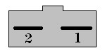 Locate wire marked N2 and new alternator plug with two wires. Using the figure to
the right, determine which wire is number 1 by looking at the connector end of the plug,
with the wires pointing away. With the notch at the top, the wire to the right is
number 1. This will be used for the charge light circuitry. Wire 2 is used for
alternators that are not selt exciting. Some alternators have this connection made
internally. This is used by the alternator to determine when to start producing
voltage. If you are unsure about your alternator, leave this wire disconnected.
After installation is complete, if alternator does not function correctly, connect
this wire (number 2) to the positive output of the alternator. If alternator
functions correctly without this connection, clip wire 2 at the base of the plug. Locate wire marked N2 and new alternator plug with two wires. Using the figure to
the right, determine which wire is number 1 by looking at the connector end of the plug,
with the wires pointing away. With the notch at the top, the wire to the right is
number 1. This will be used for the charge light circuitry. Wire 2 is used for
alternators that are not selt exciting. Some alternators have this connection made
internally. This is used by the alternator to determine when to start producing
voltage. If you are unsure about your alternator, leave this wire disconnected.
After installation is complete, if alternator does not function correctly, connect
this wire (number 2) to the positive output of the alternator. If alternator
functions correctly without this connection, clip wire 2 at the base of the plug.
Options
-
Connect N2 to 1 using Solder. Slide heat shrink over wire N2,
sliding it away from wire end. Join wires with solder. Slide heat shrink over
joint and apply heat. If joint is not covered by heat shrink, apply tape.
-
Connect N2 to 1 using Crimp. Slide heat shrink over wire N2.
Insert wire N2 into 16 gauge crimp/butt connector. Crimp. Insert wire 1
into other end of crimp/butt connector. Crimp. Slide heat shrink over
connector. Apply heat. If joint is not covered by heat shrink, use tape.
-
Install new alternator bracket using bolts and nut removed in step 5.
Install Delco Remy Delcotron 10Si or 12Si alternator. Install original alternator
belt. Tighten belt to manufacturers recommended specifications.
-
Plug in new alternator plug used in step 21 into the alternator.
-
Follow the big red wire from location 1 at the bottom of the fuse
center. This wire is the same one that spliced with Main in step 19. Follow
the wire until the end, which has a terminal connection. Connect the terminal of
this wire to the alternator output. This should be the only terminal available on
the back of the alternator. Make sure you do not connect this terminal to any
ground.
-
Follow the other big red wire from the side of the fuse center.
This wire has no junctions, and ends in a terminal. Connect this wire to the
starter solenoid positive terminal. Connect battery cable positive terminal to
starter solenoid positive terminal. With both wires on the post, attach nut, and
secure both wires. WARNING, Battery should remain disconnected.
-
Plug in spade terminal at top of starter solenoid.
-
Unplug and discard unused condensors from area of voltage regulator
and alternator.
-
Optional but highly recommended - If you have access to an ohm meter,
test the circuit using the following instructions. If not, conduct only test a.
Note, if any test fails, do not proceed. Stop and retrace the steps,
verifying all connections. Damage to property and person could result from improper
connections. Do not connect the battery until all tests pass, and directed to by
these instructions.
-
Go though the steps, and verify each connection visually. All
needed wires will be connected at this time, and should be in their correct location.
If not, correct.
-
Set your meter to Ohms, and place one test lead on ground, and the
other on the starter solenoid positive terminal. If meter reads infinite (no
continuity), proceed to next test. If meter reads anything other than infinite,
retrace steps to find where the improper connection was made.
-
Set meter to Ohms, and place one lead on starter solenoid positive
terminal, and the other lead on the alternator main output. Meter should read 0 Ohms
(maximum continuity). If meter reads 0 Ohms (plus or minus 1 or 2 ohms), proceed to
next test. If meter reads infinite or high resistance, retrace steps to find and
correct problem.
-
With meter still connected as in test b above, remove the 80 amp fuse
from the fuse center. You should see a transition from 0 Ohms to Infinite Ohms.
If this test passes, smile and proceed to next step. Good job! If step
fails, retrace steps to find and correct problem.
-
Examine wiring harness for loose and unused wires. Remove any
wires from harness that have no connection on either end. Some wires will be left
over from this process, and will remain in the harness. These wires are grounds, and
are no longer needed. If desired, the large ground from the old alternator may be
connected to the frame or block using a suitable bolt. Unused smaller grounds can be
safely taped into the harness. Form wires in harness into the desired shape,
bundling them together.
-
When wires are in the desired shape, begin taping wires. Start
by using small strips 1 foot apart to keep the wires together. Then tape from the
ends of the branches towards the main harness. Tape the wires from the bottom of the
fuse center to the main harness. Tape the wires from the starter solenoid positive
terminal towards the main harness. Tape the wires from the Alternator to the main
harness. Now tape the main harness. Tape wires from the firewall to the
alternator. Make sure to wrap tape over the tape ends from the branches. While
taping, try to overlap at least half the width of the tape. Be thorough. Leave
no exposed wiring in the harness. Leave enough exposed wire at the ends of the
branches to facilitate removal in the future. Example, leave 4 inches unwrapped wire
at the alternator to allow for ease of alternator replacement.
-
Use supplied tie wraps or existing wire tie downs to secure harness to
chassis. Make sure harness is not allowed to move or rub against metal parts.
-
Connect Negative battery terminal. Be alert for any sign of a
short. If short is present, disconnect battery immediately!
-
From inside car, examine voltmeter. Gauge should read battery
voltage. Turn key to "ON". Pull emergency brake. Verify that
both the "BRAKE" lamp and the "CHARGE" lamp should turn on. If
not, verify steps 20 through 23, and correct.
-
Start car. Rev engine to 1500 rpm. Charge lamp should
extinguish, and voltmeter should rise, indicating a charging state. Allow engine to
idle, and verify that alternator functions correctly. Some alternators don't begin
charging until a preset rpm has been reached. If you desire the alternator to charge
at all times, either change pulley sizes to a smaller pulley, or increase engine idle to a
higher rpm.
-
Enjoy a worry free charging system. Get some decadent electrical
appliances (toaster oven, laser gun, electric fence) and attach them to your Z with no
worries. You've got the power!
|